Home About Activities Tools Training Contact / Quote
Tools and software

Our tools in the BIM process

Sixteen tools, from capturing the existing to delivery: what they are for, what they receive, what they produce.
Home / Tools
The BIM process at VeraSketch

Five phases, a model that grows richer

BIM is not a piece of software but a chain: each tool receives the data from the previous step and passes it to the next, around a single digital model. Choose a phase to see the tools involved.

  1. 1Capturing the existing4 tool(s)
  2. 2Modelling4 tool(s)
  3. 3Analysis and sizing6 tool(s)
  4. 4Coordination and quantities1 tool(s)
  5. 5Fabrication and delivery1 tool(s)

Summary table

Tool1. Capturing the existing2. Modelling3. Analysis and sizing4. Coordination and quantities5. Fabrication and delivery
ReCap●○
Scene●
Agisoft Metashape●
3D scanner●
AutoCAD Plant 3D●○
Advance Steel●○
Inventor●○○
Revit●○○
Robot Structural Analysis○●
IDEA StatiCa●
Nastran In-CAD●
CAESAR II●
PV Elite●
Caneco○●
Navisworks●
3D printer●

● main phase ○ also used in this phase

Phase 1

Capturing the existing

Laser survey and photogrammetry: the existing is digitised to start from a faithful base.

ReCap

Scan processing
Phase 1 · Capturing the existingAlso: Modelling

Autodesk ReCap: imports, indexes and organises point clouds to make them usable in modelling software.

Its place in the BIM process
Bridge between capture and modelling: the indexed cloud (RCP/RCS) is referenced directly in Revit, AutoCAD or Navisworks to model "on top of" reality.
Input data
Point clouds from Scene, Metashape or other sources.
Output deliverables
ReCap projects (RCP/RCS), cropped regions of interest, lightened clouds.
Formats and exchanges
RCP, RCS, E57, LAS; links to Revit, AutoCAD, Navisworks.

Scene

Scan registration
Phase 1 · Capturing the existing

Terrestrial laser scan processing software (FARO): station registration, colourisation, cleaning and quality control of the point cloud.

Its place in the BIM process
Turns individual scans into a single, georeferenced, usable point cloud, before indexing and modelling.
Input data
Raw scans from the scanner, targets or registration points.
Output deliverables
Assembled, cleaned and colourised point cloud, registration report.
Formats and exchanges
Export to E57, RCP, ReCap-compatible formats.
Used for:Scan to BIM

Agisoft Metashape

Photogrammetry
Phase 1 · Capturing the existing

Agisoft Metashape: photogrammetry software that reconstructs point clouds, 3D meshes, orthophotos and digital models from photographs.

Its place in the BIM process
Complements the laser scanner for large areas, roofs, hard-to-reach zones or drone surveys, at a lower mobilisation cost.
Input data
Series of photographs (ground or drone) with overlap.
Output deliverables
Dense cloud, textured mesh, orthophoto, DTM.
Formats and exchanges
LAS, E57, OBJ, FBX, GeoTIFF; import into ReCap.
Used for:Scan to BIM

3D scanner

On-site 3D survey
Phase 1 · Capturing the existing

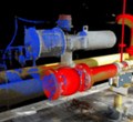
Terrestrial laser scanner that measures, contactlessly, several hundred thousand points per second and renders the existing as an accurate point cloud.

Its place in the BIM process
Entry point of the BIM process on existing assets: it provides the real (not theoretical) geometry on which all studies rely, which reduces rework and unpleasant surprises on site.
Input data
Industrial zone, unit in operation, building or structure to be surveyed.
Output deliverables
Raw scans (multiple positions), associated colour photographs.
Formats and exchanges
Manufacturer proprietary formats, exportable to E57 / RCP.
Phase 2

Modelling

Building the intelligent 3D model: piping, steel frame, building, mechanical parts.

AutoCAD Plant 3D

Piping and layout
Phase 2 · ModellingAlso: Fabrication and delivery

AutoCAD Plant 3D: 3D design of industrial units from piping catalogues and specifications, with a library of equipment and supports.

Its place in the BIM process
Core of process modelling: the 3D piping model automatically feeds isometrics, material take-offs (MTO) and layout drawings, and serves as the basis for the flexibility analysis.
Input data
P&IDs, reference drawings, point cloud of the existing, piping specifications.
Output deliverables
3D model of the facility, isometrics, MTO, layout and detail drawings.
Formats and exchanges
DWG, PCF (exchange to CAESAR II), Navisworks and ReCap links.

Advance Steel

Steel frames
Phase 2 · ModellingAlso: Fabrication and delivery

Advance Steel: 3D modelling of steel frames with parametric connections, standard sections and generation of fabrication drawings.

Its place in the BIM process
Links the study and the workshop: the structural model is the basis for execution drawings, bills of materials and numerical control files.
Input data
Structural assumptions, calculation results, survey of the existing.
Output deliverables
Frame model, general arrangement and fabrication drawings, bills of materials, NC files.
Formats and exchanges
DWG, DSTV / NC, IFC; link with Robot Structural Analysis.

Inventor

Mechanical design
Phase 2 · ModellingAlso: Analysis and sizingAlso: Fabrication and delivery

Autodesk Inventor: parametric 3D mechanical design of parts and assemblies, with drawings and bills of materials.

Its place in the BIM process
Used to design mechanical assemblies (skids, supports, tooling, parts to be printed) and to validate them before fabrication; its integrated Nastran version extends the study with calculation.
Input data
Specifications, space constraints, dimensional surveys.
Output deliverables
Part and assembly models, detail drawings, bills of materials, STL files for printing.
Formats and exchanges
STEP, IGES, DWG, STL; links with Nastran In-CAD.

Revit

Building BIM model
Phase 2 · ModellingAlso: Coordination and quantitiesAlso: Fabrication and delivery

Autodesk Revit: parametric BIM modelling platform (architecture, structure, MEP) where each object carries its properties and quantities.

Its place in the BIM process
Core of the digital model: a single model produces drawings, sections, schedules and quantities, and stays consistent with each change. It receives the point cloud to model the existing.
Input data
Point cloud, existing drawings, brief, calculation results.
Output deliverables
BIM model, drawings and sections, quantity tables, exports for coordination and calculation.
Formats and exchanges
RVT, IFC, DWG, NWC; links with Robot, Navisworks, ReCap.
Phase 3

Analysis and sizing

Verification by calculation: structures, connections, piping, vessels, electrical networks.

Robot Structural Analysis

Concrete and steel
Phase 3 · Analysis and sizingAlso: Modelling

Autodesk Robot Structural Analysis: finite element structural analysis, with reinforced concrete and steel design according to the applicable codes.

Its place in the BIM process
Validates the performance of the structure: the analytical model from the BIM model is loaded and calculated, then the selected sections are sent back to Revit or Advance Steel.
Input data
Structural model, loads, combinations, applicable codes.
Output deliverables
Calculation notes, reinforcement, section checks, optimised sections.
Formats and exchanges
Two-way exchange with Revit and Advance Steel, results export.

Used for:ConcreteSteel

IDEA StatiCa

Steel connections
Phase 3 · Analysis and sizing

IDEA StatiCa: detailed finite element verification of steel connections and concrete details, with reading of stresses and deformations.

Its place in the BIM process
Used after the global analysis to justify the nodes: bolts, welds, base plates, stiffeners, where forces concentrate.
Input data
End forces from the global analysis, connection geometry.
Output deliverables
Connection verification report, utilisation ratios, principle drawing.
Formats and exchanges
BIM links with Robot, Revit and Advance Steel.

Used for:Steel

Nastran In-CAD

Finite elements
Phase 3 · Analysis and sizing

Nastran In-CAD: finite element solver integrated into Inventor for static, modal and buckling analysis of parts and assemblies.

Its place in the BIM process
Allows a part or mechanical equipment to be justified directly in the design environment, before fabrication or printing.
Input data
Inventor model, materials, boundary conditions, loads.
Output deliverables
Stresses, displacements, natural frequencies, safety factors.
Formats and exchanges
Integrated into Inventor; results exportable to a report.

CAESAR II

Piping flexibility
Phase 3 · Analysis and sizing

CAESAR II: flexibility and stress analysis of piping under expansion, weight, pressure, wind and earthquake, according to industrial piping codes.

Its place in the BIM process
Validates the routing and supports of the piping model: it checks stresses in the lines and loads on equipment nozzles, then the routing is adjusted in the 3D model.
Input data
Routing from the piping model, service conditions, material specifications.
Output deliverables
Stress report, loads at supports and nozzles, support recommendations.
Formats and exchanges
Import of the routing via neutral file (PCF) from Plant 3D.

Used for:Facilities

PV Elite

Pressure vessels
Phase 3 · Analysis and sizing

PV Elite: sizing and verification of pressure vessels (tanks, drums, exchangers, columns) with their nozzles, supports and lifting cases.

Its place in the BIM process
Guarantees the mechanical compliance of the equipment in the model: thicknesses, openings, external loads, before their integration into the layout.
Input data
Process data, design conditions, vessel geometry.
Output deliverables
Calculation note, selected thicknesses, check of nozzles and supports.
Formats and exchanges
Calculation reports; geometries taken into the 3D model.

Used for:Facilities

Caneco

LV electrical calculations
Phase 3 · Analysis and sizingAlso: Modelling

Caneco BT: low voltage electrical installation calculation — power balances, cable cross-sections, voltage drops, protection and selectivity.

Its place in the BIM process
Sizes the electrical network that will then be laid out on the drawings (cable trays, switchboards) and documented by single-line diagrams.
Input data
Load list, distribution diagram, earthing system, cable lengths.
Output deliverables
Calculation notes, single-line diagrams, cable and protection lists.
Formats and exchanges
Spreadsheet and drawing exports; results reused in AutoCAD.

Used for:Electrical
Phase 4

Coordination and quantities

Model aggregation, clash detection, 4D simulation and 5D quantity take-offs.

Phase 5

Fabrication and delivery

Execution drawings, printed prototypes, as-built file (DOE).

3D printer

Rapid prototyping
Phase 5 · Fabrication and delivery

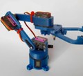
3D printer: additive manufacturing of prototypes, models, jigs and small-series parts from digital models.

Its place in the BIM process
Materialises the model: shape, assembly and ergonomics are validated on a real part before committing to final fabrication, or custom tooling is produced.
Input data
STL / 3MF files from Inventor or a scan model.
Output deliverables
Prototypes, models, jigs, small series.
Formats and exchanges
STL, 3MF.
Used for:3D printing

Which tool for your project?

We choose the toolchain suited to your need: survey, model, calculation or prototype.